
Optical transport networks have been migrating from SONET technology to WDM architectures over the past 5–10 years. Deploying WDM systems has allowed carriers to tap enormous capacity by carrying multiple wavelengths over a single fiber. For carriers, this means significant cost savings compared to the cost of deploying single-channel networks, or of over laying multiple networks for each service offering. As this transition to WDM architectures occurred, it became painfully obvious that early WDM implementations lacked many key features required to properly operate and maintain these optical networks. With early WDM platforms many features, such as performance monitoring, fault detection and isolation, a standard multiplexing hierarchy and standard communication channels, were either missing or implemented in a proprietary fashion by each WDM equipment vendor.
The Optical Transport Network (OTN) standards, defined by the ITU-T G.709 standards committee, were developed to add SONET-like performance monitoring, fault detection, communication channels, and multiplexing hierarchy to WDM wavelengths. The primary benefits of OTN include:
• Enhanced OAM for wavelengths
• Universal container supporting any service type
• Standard multiplexing hierarchy
• End-to-end optical transport transparency of customer traffic
• Multi-level path OAM
The benefits that made SONET a robust optical transport technology, including a standardized mapping of client signals, enhanced performance monitoring at multiple layers, comprehensive fault detection and isolation, and embedded communications channels, were all missing from early WDM networks. Each
Vendor implemented their own proprietary methods of mapping client traffic, of detecting/isolating alarm faults, and providing optical performance monitoring. For single-carrier networking only one vendor’s equipment, this lack of standardization wasn’t a serious problem. However, as optical networks grew and became inter-connected across network boundaries, the lack of OAM standardization for WDM became
a huge liability. Essentially, the industry lost all of the benefits SONET provided for large, multi vendor interconnected networks.
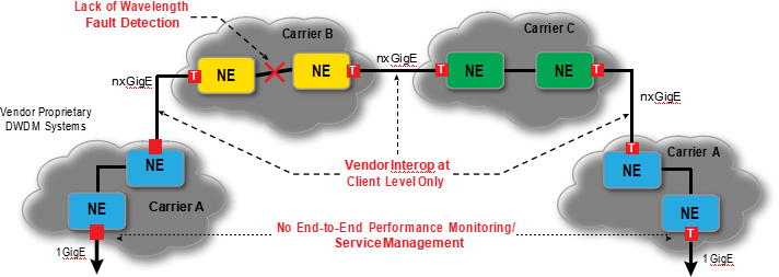
Without a common mapping structure, client traffic had to be de-multiplexed into its lowest common form at carrier boundaries. For example, a carrier providing GbE services with an GbE muxponder card had to break the signal back into individual GbEs at carrier boundaries, as opposed to simply handing off 10 Gbps wavelengths.
Without standard fault detection and alarm indication signals, a fault in one portion of the network could not be communicated to other portions of the network, especially across carrier boundaries. This led to the classic condition of a customer complaining about receiving a bad signal, without the carrier having knowledge or awareness of the fault condition.
Finally, without a function equivalent to “path layer monitoring,” there was no way to provide an end-to- end assurance (SLA) for customer traffic. All three issues are highly problematic for operating a network and selling mission-critical services.
End Customer End Customer
![]()
Figure 1: The need for OTN standards
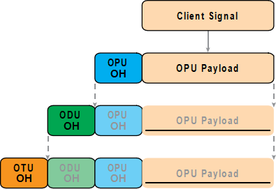
Adding OAM capabilities to WDM networks required creating a frame structure to“digitally wrap” or “encapsulate” the payload, which is the basis of the ITU-T G.709 OTN standards, and commonly referred to as G.709 Digital Wrapper. The OTN frame is very similar to a SONET frame in its structure and format.
There are three overhead areas in an OTN frame: the Optical Payload Unit (OPU) overhead, the Optical Data Unit (ODU) overhead, and the Optical Transport Unit (OTU) overhead. These overhead bytes provide path and section performance monitoring, alarm indication, communication, and protection switching capabilities. One additional feature is the inclusion of a Forward Error Correction (FEC) function for each frame. The FEC improves the Optical Signal-to-Noise Ratio (OSNR) by 4 to 6 dB, resulting in longer spans and fewer regeneration requirements.

![]()
Figure 2: OTN frame structure
A client signal is mapped into the OPU payload, with the OPU overhead providing information on the type of signal mapped into the payload and the mapping structure. Although a bit confusing with SONET terminology, the“P” in OPU does not stand for “path” and the OPU does not provide any path- layer monitoring functions.
The ODU overhead adds optical path-level monitoring, alarm indication signals, automatic protection switching bytes, and embedded data communications channels (GCC1/GCC2). The ODU is the basic payload that is electronically groomed and switched within an OTN network.
![]()
Figure 3: OTU client signal mapping
The OTU overhead adds bytes to provide
optical section layer PM, alarm indication, and the GCC0 data communications channel. The OTU represents a physical optical interface or port, such as an OTU2 (10 Gbps), OTU3 (40 Gbps) and OTU4 (100 Gbps).
Within the OTN overhead, the path monitoring bytes provide a critical function in monitoring end-to- end signal quality, enabling carriers to guarantee customer Service Level Agreements (SLAs). In large, interconnected networks, such as those shown in Figure 4, it’s very beneficial to have multiple path monitoring points.
The traditional OTN path monitoring bytes allow carriers to perform end-to-end signal monitoring across the overall network, as shown in Figure 4. In large networks constructed over wide geographical areas, it’s very common for multiple carriers to be transporting a signal, each providing transport services across their respective geographical area or “cloud.” These additional carriers have requirements for monitoring the path layer as the signal enter their“cloud,” to provide service assurance to the end-to-end carrier. OTN enables path-layer monitoring at multiple, user-defined end points, and it is one of the more powerful features of OTN. TCM bytes provide this user-defined path monitoring function. There are up to six different levels of TCM bytes available in the OTN overhead, labeled TCM1 through TCM6. These bytes allow carriers to define their own path layers. For example, Carrier B could use TCM1 to perform path monitoring at the entry and exit points of its network. Likewise, Carrier C could use TCM2 to perform path monitoring on the signal as it enters and exits the Carrier C cloud.
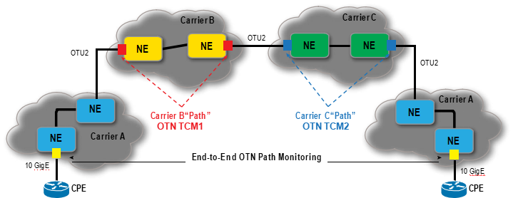
Figure 4: OTN tandem monitoring
Originally, the G.709 digital wrapper was primarily used for transporting 10 Gbps wavelengths, enabling improved performance due to the FEC and improved OAM due to the OTN overhead bytes and standard frame structure. Lower rate signals, such as 4 x OC-48 and 8 x GbE were simply multiplexed into 10 Gbps payloads and then encapsulated into the OTN frame. Since each vendor had their own method of multiplexing lower-rate signals into 10 Gbps wavelengths, there was no way to share these aggregate 10 Gpbs wavelengths in large multi vendor networks. This lack of common underlying mapping structures forced carriers to demultiplex each 10 Gbps or 40 Gbps wavelength at every core aggregation node and at every network boundary, which was very in efficient and costly.
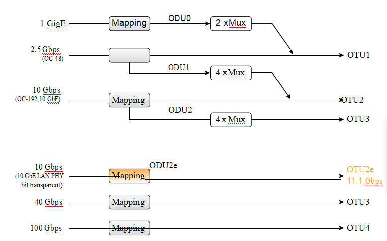
OTN standards evolved to include a standard multiplexing hierarchy, defining exactly how the lower- rate signals map into the higher-rate payloads. This allows any OTN switch and any WDM platform to electronically groom and switch lower-rate services within 10 Gbps, 40 Gbps, or 100 Gbps wavelengths, without the need for external wavelength demultiplexing and manual interconnects.
The diagram depicted is not the complete OTN mapping structure. It is a simplified version showing some of the most common mappings. As an example, a 2.5 Gbps signal (OC-48) is mapped into an OTU1 frame. Four of these 2.5 Gbps signals can be mapped into an OTU2 frame.
![]()
Figure 5: Simplified OTN mapping diagram
The smallest OTN container defined is the ODU0 payload, operating at 1.25 Gbps. Originally, the ODU0 payload was intended to support 1 GbE signals, but has been extended to include additional mapping options for other services, such as OC-3 and OC-12 signals. While the ODU0 can be used for signal types other than 1 GbE, only a single service is allowed per ODU0 container. Mapping a single OC-3 (155 Mbps) or a single OC-12 (622 Mbps) service into a 1.25 Gbps ODU0 container is not a very efficient use of the bandwidth, so ODU service applications below 1 Gbps may be very limited.
As signal rates increased to 40 Gbps (OTU3) and 100 Gbps (OTU4), additional mapping structures have been defined for mapping ODU0, ODU1, ODU2, and ODU3 signals into these higher-rate payloads. The key point is that the optical transport industry and all vendors’ products now have a common standard of multiplexing and demultiplexing services for WDM networks, enabling multivendor interoperability and OTN switching and grooming.
Up to this point, the G.709 OTN standard was primarily used in optical transport applications, providing standard performance monitoring, fault detection, embedded communication channels, and FEC for WDM networks. However, as OTN standards evolved to include standard, hierarchal mapping structures, the technology is now expanding into switching and aggregation applications.
Most large carrier networks have aggregation switches deployed at major gateway locations, usually at metro and long-haul network junctions. These aggregation switches allow them to efficiently aggregate and groom traffic as it enters and exits their ultra-long haul network.
These aggregation/grooming nodes are prime candidates to be upgraded to large OTN switches, offering several key benefits:
• OTN switches operate at the OTU layer. They are independent of the traffic type carried within the payload, so the network becomes transparent to any underlying services and protocols
• Switching at the ODU layer maintains the end-to-end optical performance and alarm monitoring
• Utilizing standard OTN mapping structures, OTN switching allows efficient grooming of traffic and high utilization of the ULH wavelengths.
Deployment of these OTN aggregation switches between the metro and LH networks will further drive OTN muxponding and switching requirements into the metro and access parts of the network, so that carriers can realize the benefits and efficiencies of end-to-end OTN networks.
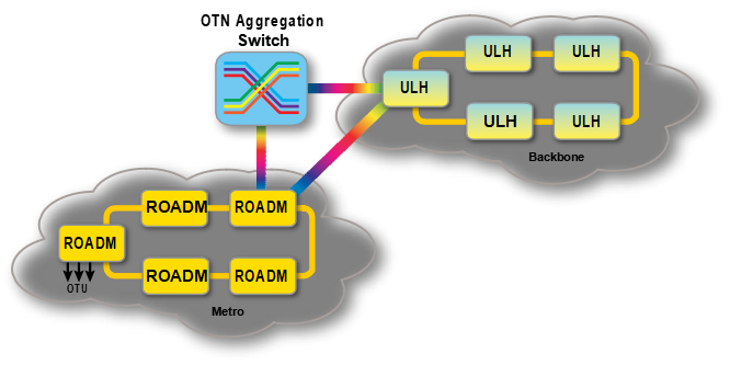
Figure 6: OTN aggregation and switching
Within the metro space, the industry is still debating the best method for aggregating and transporting OTN signals. For point-to-point private-line services at 10 Gbps or 40 Gbps rates, transponders with G.709 OTN encapsulation are well suited to the application and fully supported on existing ROADM platforms. For lower-rate signals, at 1 GbE and 2.5 Gbps, simple OTN muxponders might be suitable, especially in applications where there are limited numbers of 1 Gbps and 2.5 Gbps private-line services.
As the number of 1 GbE and 2.5 Gbps services increases within a metro area, muxponding becomes a less efficient approach compared to distributed OTN switching at each node. A combination of muxponding and integrated OTN switching will likely be deployed on any next-generation metro architecture.

Access Metro Regional/ULH
![]()
Figure 7: End-to-end OTN network
OTN technology is evolving from its traditional role of encapsulating wavelengths for WDM optical transport to core switching and aggregation at major gateway locations. As OTN core switches are deployed, this will drive OTN muxponding, aggregation, and switching applications deeper into the metro and access parts of the network. As this transition occurs, the question arises of how OTN technology and Packet ONP technology should coexist within a metro space.
Packet ONPs are designed to efficiently aggregate and switch Ethernet services, along with legacy TDM/ SONET services. They are extremely efficient in providing thousands of high quality, Connection-Oriented Ethernet services (10 Mbps–1 GbE) over metro networks.
OTN is effective and efficient for very high-rate private-line services, such as those operating >1 GbE. Since the smallest OTN container is the ODU0 at 1.25 Gbps, anything less than 1 GbE is not a very efficient use of the OTN bandwidth. For these high-rate private-line services, they can benefit from OTN’s enhanced end-to- end OAM and transparency to end-user services. OTN complements Packet ONPs, and will be incorporated into these devices along with their Ethernet and TDM aggregation and switching capabilities.
Early WDM implementations lacked many of the key OAM features that existed in SONET, causing difficulties in operating and maintaining WDM networks especially in large, interconnected multivendor networks. The OTN standards were designed to provide a robust set of OAM features for WDM architectures, including performance monitoring, fault detection, forward error correction, embedded communications channels, and a standard mapping structure for multiplexing lower rate signals into higher-speed payloads. OTN is already widely deployed for transport applications, as a digital wrapper on 10 Gbps and 40 Gbps transponder signals. However, OTN technology is quickly evolving into switching and aggregation roles, with the first applications being large-core OTN switch nodes at major gateway locations. Once deployed, these large OTN aggregation nodes will accelerate the need for OTN muxponding and switching within the metro and access parts of the network. OTN is a complementary technology to COE and packet optical networking and is best suited for carrying high-rate private line services within metro areas.
Sharetop commit to supply customers with Tier-1 products and quality services, develop new products continuously as per technology trend and customer requirement, expand the market share for the mutual benefits of our partners, and consequently embrace a better future.
Acronyms

联系方式

隐私保护 |
法律声明 |
在线留言 |
网站导航 |
网站地图 |
文档下载 | 咨询热线:0755-27524036 |
订阅
深圳纤亿通科技有限公司版权所有 转载必究 Copyright 2010-2019 poptimes CO.,Ltd. All rights reserved.
备案号:粤ICP备14020946号
友情链接: 光创未来| fiber168| 纤亿通光源放大器网站| 纤亿通光模块网站| 纤亿通保偏无源器件网站| 纤亿通OTN网站

