纤亿通-专注光纤通讯产品研发,欢迎您的光临


咨询热线:0755-27524036


- Products description -
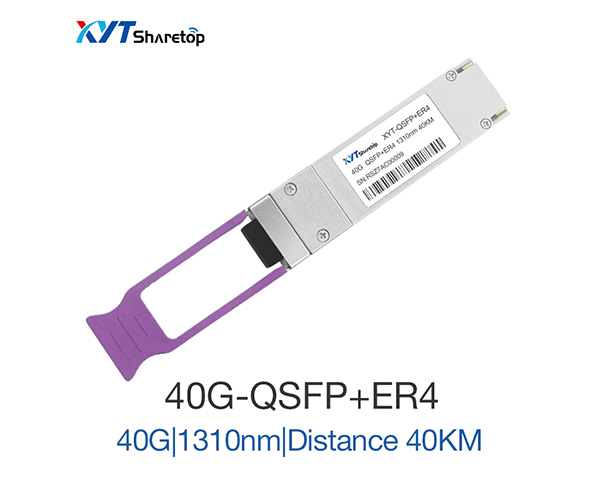
This product is a transceiver module designed for 40km optical communication
applications. The design is compliant to 40GBASE-ER4 of the IEEE P802.3ba standard. The
module converts 4 inputs channels (ch) of 10Gb/s electrical data to 4 CWDM optical
signals, and multiplexes them into a single channel for 40Gb/s optical transmission.
Reversely, on the receiver side, the module optically de-multiplexes a 40Gb/s input into 4
CWDM channels signals, and converts them to 4 channel output electrical data.
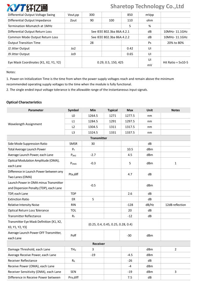
The central wavelengths of the 4 CWDM channels are 1271, 1291, 1311 and 1331 nm as
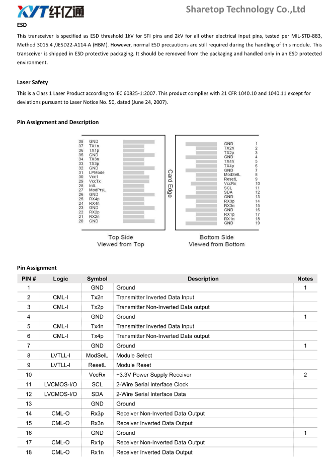
members of the CWDM wavelength grid defined in ITU-T G.694.2. It contains a duplex LC
connector for the optical interface and a 38-pin connector for the electrical interface. To
minimize the optical dispersion in the long-haul system, single-mode fiber (SMF) has to be
applied in this module.
The product is designed with form factor, optical/electrical connection and digital
diagnostic interface according to the QSFP+ Multi-Source Agreement (MSA). It has been
designed to meet the harshest external operating conditions including temperature,
humidity and EMI interference.
- Product Features -
Compliant with 40G Ethernet IEEE802.3ba and 40GBASE-ER4 Standard QSFP+ MSA compliant.
Compliant with QDR/DDR Infiniband data rates.
Up to 11.2Gb/s data rate per wavelength.
4 CWDM lanes MUX/DEMUX design.
Up to 40km transmission on single mode fiber (SMF).
Operating case temperature: 0 to 70℃.
Maximum power consumption 3.5W.
LC duplex connector.
RoHS compliant.
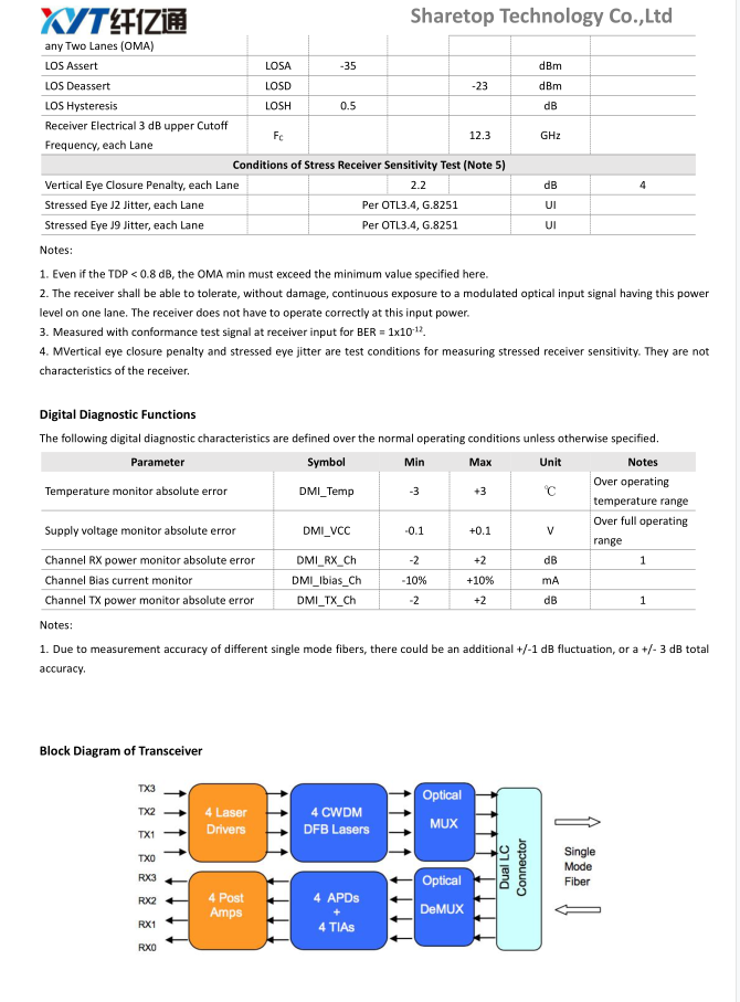
Functional Description
This product converts the 4-channel 10Gb/s electrical input data into CWDM optical signals (light), by a driven 4-wavelength
Distributed Feedback Laser (DFB) array. The light is combined by the MUX parts as a 40Gb/s data, propagating out of the transmitter
module from the SMF. The receiver module accepts the 40Gb/s CWDM optical signals input, and de-multiplexes it into 4 individual
10Gb/s channels with different wavelength. Each wavelength light is collected by a discrete photo diode, and then outputted as
electric data after amplified first by a TIA and a post amplifier. Figure 1 shows the functional block diagram of this product.
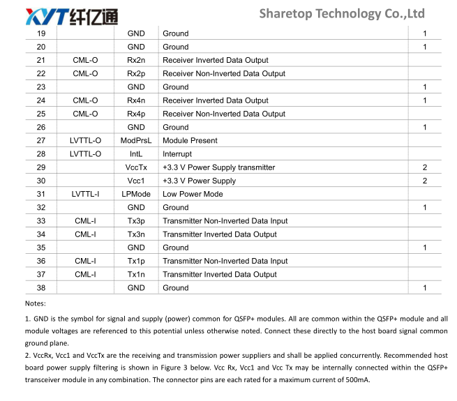
A single +3.3V power supply is required to power up this product. Both power supply pins VccTx and VccRx are internally connected
and should be applied concurrently. As per MSA specifications the module offers 7 low speed hardware control pins (including the
2-wire serial interface): ModSelL, SCL, SDA, ResetL, LPMode, ModPrsL and IntL.
Module Select (ModSelL) is an input pin. When held low by the host, this product responds to 2-wire serial communication
commands. The ModSelL allows the use of this product on a single 2-wire interface bus – individual ModSelL lines must be used.
Serial Clock (SCL) and Serial Data (SDA) are required for the 2-wire serial bus communication interface and enable the host to access
the QSFP+ memory map.
The ResetL pin enables a complete reset, returning the settings to their default state, when a low level on the ResetL pin is held for
longer than the minimum pulse length. During the execution of a reset the host shall disregard all status bits until it indicates a
completion of the reset interrupt. The product indicates this by posting an IntL (Interrupt) signal with the Data_Not_Ready bit
negated in the memory map. Note that on power up (including hot insertion) the module should post this completion of reset
interrupt without requiring a reset.
Low Power Mode (LPMode) pin is used to set the maximum power consumption for the product in order to protect hosts that are
not capable of cooling higher power modules, should such modules be accidentally inserted.
Module Present (ModPrsL) is a signal local to the host board which, in the absence of a product, is normally pulled up to the host
Vcc. When the product is inserted into the connector, it completes the path to ground through a resistor on the host board and
asserts the signal. ModPrsL then indicates its present by setting ModPrsL to a “Low” state.
Interrupt (IntL) is an output pin. “Low” indicates a possible operational fault or a status critical to the host system. The host
identifies the source of the interrupt using the 2-wire serial interface. The IntL pin is an open collector output and must be pulled to
the Host Vcc voltage on the Host board.

隐私保护 |
法律声明 |
在线留言 |
网站导航 |
网站地图 |
文档下载 | 咨询热线:0755-27524036 |
订阅
深圳纤亿通科技有限公司版权所有 转载必究 Copyright 2010-2019 poptimes CO.,Ltd. All rights reserved.
备案号:粤ICP备14020946号
友情链接: 光创未来| fiber168| 纤亿通光源放大器网站| 纤亿通光模块网站| 纤亿通保偏无源器件网站| 纤亿通OTN网站