Welcome to Sharetop Technology Co.,ltd.

Hotline:+86-0755-27524036

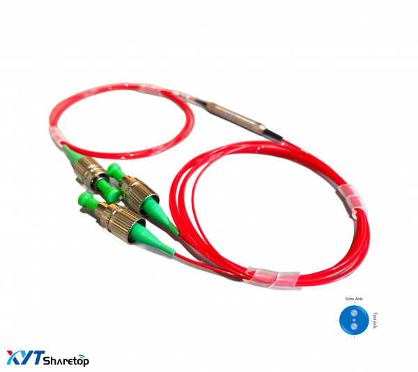
XYT-PM-CWDM
【NO.】PMCWDM-3ort-01
Filter slide type PM CWDM(1270~1610nm)
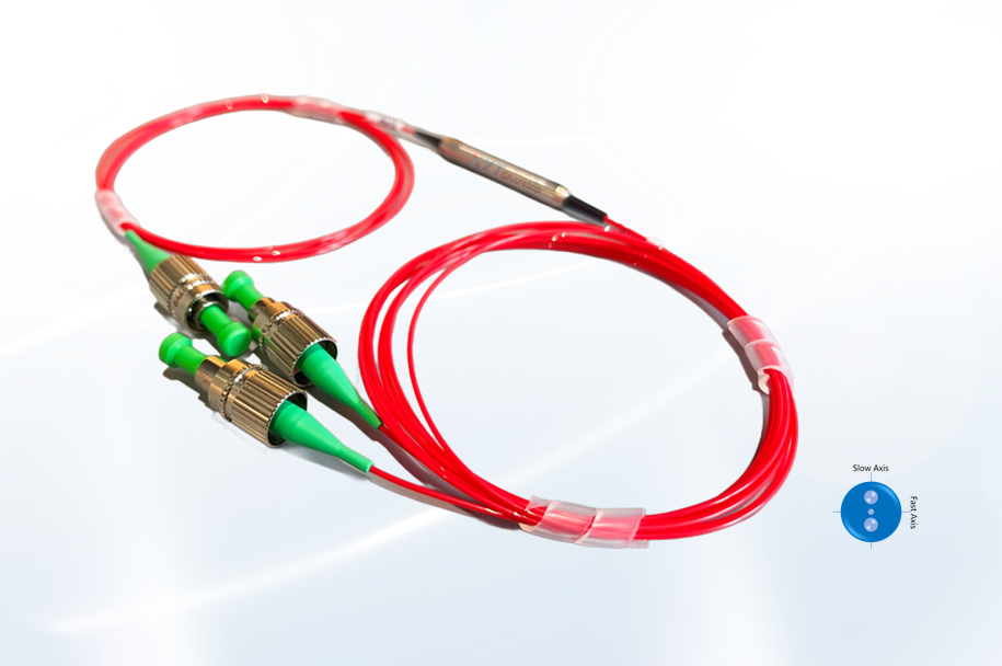
l Low insertion loss l PM1300/PM1550 fiber
l High stability and reliability l Bare fiber, sleeve, and joint types are optional
l Compact structure l Acceptable power options
l Center wavelength optional l Multiple customizable options
l Center wavelength: ITU or ITU+1
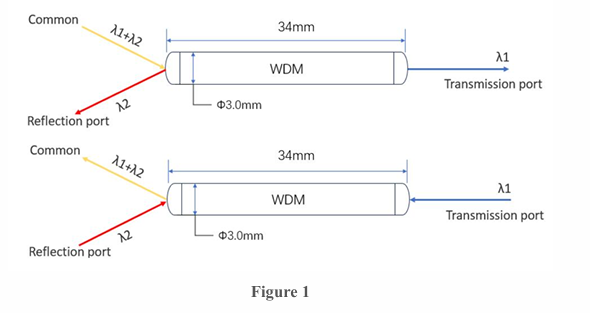
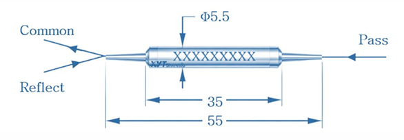
CWDM (TFF) wavelength division multiplexer is a device that can couple two or more different wavelengths of optical signals in one core fiber for transmission, and vice versa, can separate and demultiplexing two or more different wavelengths of optical signals in one core fiber separately. As shown in the figure, two different beams of light are input from the common end. WDM devices allow one specific wavelength of light to be transmitted and output at the transmitting end, while the remaining wavelengths are reflected and coupled to the reflecting end for output, which is the process of light splitting. Similarly, the optical path of WDM devices is reversible.
Dielectric film filter (TFF) adopts the principle of thin film interference, which causes strong reflection of certain wavelengths of light on the thin film and prevents it from passing through, while other wavelengths of light can pass through the thin film. To improve reflection efficiency, dielectric film filter chips usually use multiple layers of thin films (usually 50-100 layers), which interfere with each other to pass a certain wavelength and reflect other wavelengths.
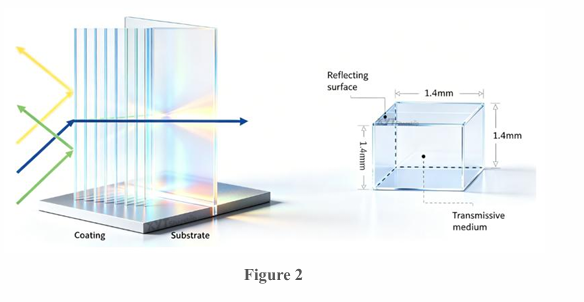
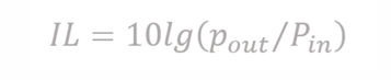
Insertion loss calculation: the ratio of optical power between input and output ports
1x2 | |||
Center wavelength (nm) | 1270~1610nm or 1271~1611nm( ITU or ITU+1) | ||
Wavelength range (nm) | 1260~1650 | ||
Channel spacing (nm) | 20 | ||
Bandwidth range (nm) | ±6.5 | ±7.5 | |
Transmission wavelength | Insertion loss (dB) | ≤0.6 | |
Adjacent isolation (dB) | ≥30 | ||
Non adjacent isolation (dB) | ≥40 | ||
Reflection wavelength | Insertion loss (dB) | ≤0.4 | |
Isolation level (dB) | ≥12 | ||
Return loss (dB) | 50 | ||
Directionality (dB) | 55 | ||
Minimum extinction ratio (dB) | 20 | ||
Maximum wavelength thermal stability (nm/℃) | 0.002 | ||
Maximum insertion loss thermal stability (dB/℃) | 0.005 | ||
Enduring power (W) | 0.5、1 | ||
Connector Type | FC/APC Or other | ||
Fiber Type | PM1300、PM1550 | ||
Fiber length (m) | 1M Or other | ||
Package size (mm) | Ø5.5 x 35 | ||
ABS-Box | |||
Working temperature (℃) | -5~+70 | ||
Storage temperature (℃) | -40~+85 | ||
Maximum tensile force (N) | ≤5 | ||
*The specification is without a connector, and the test data indicator is 25 ℃.
*For devices with connectors, IL is 0.3dB high, RL is 5dB low, and ER is 2dB low. Align the key key with the slow axis.
*For different power parameters, the product adopts different packaging sizes.
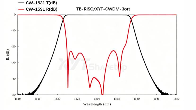
Spectrum diagram (dB):
Ordering information: | ||||
PMCWDM= Polarization maintaining wavelength division multiplexer | XYT-PMCWDM-A-B-C-D-E-F-G | |||
A=Structure | 1X2=1X2 | …… | SS= customizable | |
B=working wavelength | 27=T1270nm | 29=T1290nm | …… | S= Optional |
C=Fiber optic type | P13= PM1310 | P15= PM1550 | …… | S= Optional |
D=Type of casing | 0.25=250μm | 0.9=900μm | …… | S= Optional |
E=Fiber length | 1M=1 meter | 2M=2meter | …… | SS= customizable |
F=Type of connector | FA=FC/APC | SA=SC/APC | N= None | S= Optional |
G=withstand power | 05=0.5W | 1=1W | …… | S= Optional |
H=working axis | F=fast axis cutoff | B=Dual axis work | …… | S= Optional |
Fiber optic characteristics:
Type | PM1300-XP | PM1550-XP |
Operating Wavelength | 1270 – 1625 nm | 1440 – 1625 nm |
numerical aperture | 0.120 | 0.125 |
Mode field diameter (Gaussian) | 9.3 ± 0.5 µm @ 1300 nm | 10.1 ± 0.4 µm @ 1550 nm |
cutoff wavelength | 1210 ± 60 nm | 1380 ± 60 nm |
Loss attenuation | ≤ 1.0 dB/km @ 1300 nm | ≤ 1.0 dB/km @ 1550 nm |
Beat frequency length (nominal) | ≤ 4 mm @ 1300 nm | ≤ 5.0 mm @ 1550 nm |
Normalized Crosstalk | ≤ - 40.0 dB at 4 m @ 1300 nm | ≤ - 40.0 dB at 4 m @ 1550 nm |
≤ - 30.0 dB at 100 m @ 1300 nm | ≤ - 30.0 dB at 100 m @ 1550 nm | |
Cladding Diameter | 125.0 ± 1.0 µm | 125.0 ± 1.0 µm |
Core diameter | 8.0 µm | 8.5 µm |
Coating layer diameter | 245.0 ± 15.0 µm | 245.0 ± 15.0 µm |
Deviation of cladding/coating layer | < 5.0 µm | < 5.0 µm |
Core/cladding concentricity deviation | ≤ 0.50 µm | ≤ 0.50 µm |
Coating layer material | Acrylate | Acrylate |
Operating temperature | -40 to 85 °C | -40 to 85 °C |
Level of strength testing | ≥ 200 kpsi (1.4 GN/m² | ≥ 200 kpsi (1.4 GN/m² |
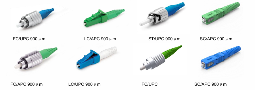
Physical character:
Type | Instructions | Notes |
durability test | Typical insertion loss variation<0.1 dB | The typical value change of optical signal loss after 500 insertions and removals of the connector is less than 0.1 dB |
Number of fiber cores | Single work (1-core fiber optic) | The connector is a single core structure, suitable for independent connection of a single optical fiber |
Applicable cable type | 900 µ m to 3 mm | The connector is compatible with optical fibers or cables with an outer diameter between 900 microns and 3 millimeters |
Insert material | Zirconia (ZrO ₂) | The connector plug is made of zirconia ceramic material, which has high wear resistance and stability |
Optical characteristics:
Parameter indicators | Single mode | Multi mode | |||
Low loss UPC | Standard UPC | Low loss APC | Standard APC | Standard MM | |
Typical insertion loss (dB) | 0.05 | 0.08 | 0.07 | 0.1 | 0.1 |
Maximum insertion loss (dB) | 0.15 | 0.2 | 0.15 | 0.25 | 0.2 |
Typical Return Loss (dB) | ≥55 | ≥65 | ≥25 | ||
Insert diameter (µ m) | 125 µm | 127µm | |||
Working temperature (℃) | 40°C to +75°C | ||||
* This statement applies to the product description, 'Our company's products will be continuously updated, and we reserve the right to modify relevant indicators at any time without prior notice.

|
Products damaged due to human or non-use of other causes of improper,we promises one year warranty and lifetime maintenance,but the unauthorized disassembly equipment caused damage is not covered under warranty and returned within range. |

|
Under normal use,if there are product quality problems,or not work normally,we provide free repair or replacement service within one year;Within three years more than one year,we provide to collect the material cost,maintenance free. Repair warranty period of three years from the freight borne by each of the parties.After three years of warranty,the material cost,maintenance,freight(refers to the product of the two-way shipping to and from)shall be borne by the user. |

|
We promise that the product we provide can meet the performance requirements of users , and it is supplied by the user's sample request. |